
Reading Sensors
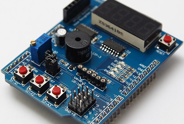
This is Part 2 of the Applied Hackatronics Series for the Arduino Multi-function shield (following on from Part 1), and shows how the multi-function shield library can be used to read values from external sensors, such as temperature, sonar and motion sensors, and how to process electronic pulses from an external source. If you haven’t already done so, you’ll need to download the source code and install the libraries using the links in the introduction.
By following the Hackatronics series, you agree to do so at your own risk, and agree to take full responsibility for any loss or damages you may incur upon yourself or others.
Counting pulses
The multi-function shield library has support for counting pulses (up to 500Hz) applied to an input pin of the Arduino. The counting of pulses is managed in the background using interrupts, which allows your application to focus on performing its main task. After uploading this sketch, repeatedly press button 1 to generate the pulses and see a reading of the press rate on the digit display.
#include <MultiFuncShield.h>

void setup() {
  // put your setup code here, to run once:
  MFS.initialize();  // initialize multi-function shield library

  MFS.initPulseInCounter(
      BUTTON_1_PIN,      // use button 1 as means of generating pulses.
      1500,              // the number of milliseconds to wait for a pulse, before resetting pulse in period to 0.
      LOW                // trigger pulse on LOW input.
  );
}

void loop() {
  // put your main code here, to run repeatedly:

  // Get the period of the most recent pulse (in milliseconds).
  // NOTE: pulse measurements are actually performed using interrupts.
  unsigned int pulsePeriodMs = MFS.getPulseInPeriod();

  if (pulsePeriodMs == 0)
  {
    MFS.write(0.0, 1);
  }
  else
  {
    MFS.write(1000.0 / pulsePeriodMs, 1);  // calculate pulses per second. Display to 1 decimal place.
  }
}
Reading the temperature using an LM35 sensor
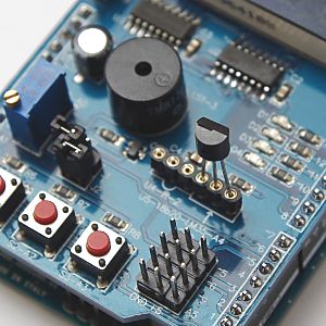
The multi-function shield has a socket for accepting an LM35 temperature sensor, which must be inserted correctly, otherwise you may irreparably damage your Arduino, or computer connected to it. You will know when the sensor is incorrectly connected, because it will become very hot. The multi-function shield library provides three levels of filtering for smoothing the readings from this sensor.
#include <MultiFuncShield.h>

// NOTE: make sure jumper J1 is removed from shield, and that LM35 is inserted correctly.

void setup() {
  // put your setup code here, to run once:
  MFS.initialize();  // initialize multi-function shield library

  // Initialize using a low pass filter.
  // Choose either: SMOOTHING_NONE, SMOOTHING_MODERATE or SMOOTHING_STRONG
  MFS.initLM35(SMOOTHING_MODERATE);
}

void loop() {
  // put your main code here, to run repeatedly:

  int tempCentigrade = MFS.getLM35Data(); // get centigrade in 1/10 of degree.
  MFS.write((float)tempCentigrade / 10, 1);  // display temp to 1 decimal place.
  delay(100);
}
Using an HC SR04 sonar module
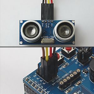
When using an HC SR04 sonar module, it is advisable to use the multi-function shield library to read and calculate distance values if interrupts are turned on. The reason for this is that the library’s interrupt service routine affects the timing requirements of this sonar module, and as such the library compensates for it. The library also offers three levels of filtering for smoothing the readings from the sonar module. The trigger and echo pins of the sonar module are connected to Arduino pins 5 and 6 respectively.
#include <MultiFuncShield.h>

const int TrigPin = 5;
const int EchoPin = 6;

void setup() {
  // put your setup code here, to run once:

  pinMode(TrigPin, OUTPUT);
  pinMode(EchoPin, INPUT);

  MFS.initialize();  // initialize multi-function shield library

  // initialize with low pass filter: SMOOTHING_NONE, SMOOTHING_MODERATE or SMOOTHING_STRONG
  MFS.initSonar(SMOOTHING_MODERATE);
}

void loop() {
  // put your main code here, to run repeatedly:
  MFS.write((int)MFS.getSonarDataCm(TrigPin, EchoPin));
  delay(100);
}
Getting data from an MPU6050 motion sensor
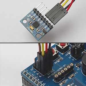
The multi-function shield does not expose the hardware I2C pins of some Arduino boards, such as the Leonardo. The image above shows the pin connections for software I2C, which is no longer supported. The following sketch uses the shield library to read raw values from the MPU6050 sensor using the Wire library. Download the full source code to upload the sketch to an Arduino, after which press button 1 on the shield to toggle reporting of sensor data, and press button 2 to cycle through acceleration, gyro and temperature values.
#include <Wire.h>
#include <MultiFuncShield.h>

#include "I2C.h"
#include "MPU6050.h"

MPU6050 MPU;
void displayHeading(byte mode);

void setup() {
  Serial.begin(9600);

  // put your setup code here, to run once:

  // Use hardware I2C
  Wire.begin();
  I2C1.initialize(&Wire);
  MPU.initialize(&I2C1, MPU_DEFAULT_ADDRESS);

  MFS.initialize();
  MFS.write("Acc");
}

byte displayValues = true;
byte displayMode = 0;


void loop() {
  // put your main code here, to run repeatedly:

  byte btn = MFS.getButton();

  // Use button 1 to toggle reporting of sensor values.
  if (btn == BUTTON_1_PRESSED)
  {
    displayValues = !displayValues;

    if (displayValues)
    {
      displayHeading(displayMode);
    }
    else
    {
      MFS.write("Off");
    }
  }

  if (displayValues)
  {
    // Use button 2 to cycle though the display modes.
    if (btn == BUTTON_2_PRESSED)
    {
      displayMode++;

      if (displayMode == 3)
      {
        displayMode = 0;
      }

      displayHeading(displayMode);
    }

    if (displayMode == 0)
    {
      // display raw acceleration values.
      MPU.getAccelRaw();
      Serial.print((float)MPU.accel_X_Raw / MPU.accelScaleValue);
      Serial.print("\t");
      Serial.print((float)MPU.accel_Y_Raw / MPU.accelScaleValue);
      Serial.print("\t");
      Serial.print((float)MPU.accel_Z_Raw / MPU.accelScaleValue);
      Serial.print("\t\n");
    }
    else if (displayMode == 1)
    {
      // display raw gyrovalues
      MPU.getGyroRaw();
      Serial.print((float)MPU.gyro_X_Raw / MPU.gyroScaleValue);
      Serial.print("\t");
      Serial.print((float)MPU.gyro_Y_Raw / MPU.gyroScaleValue);
      Serial.print("\t");
      Serial.print((float)MPU.gyro_Z_Raw / MPU.gyroScaleValue);
      Serial.print("\t\n");
    }
    else if (displayMode == 2)
    {
      // display temperature value.
      Serial.println((float)MPU.getTemp10th() / 10);
    }
  }

  delay(50);
}

void displayHeading(byte mode)
{
  if (mode == 0)
  {
    Serial.println("Acceleration in g (1g = 9.8 m/s/s)");
    Serial.println("X\tY\tZ");
    MFS.write("Acc");
  }
  else if (mode == 1)
  {
    Serial.println("Gyro angular velocity in degrees / second");
    Serial.println("X\tY\tZ");
    MFS.write("Gyro");
  }
  else if (mode == 2)
  {
    Serial.println("Temperature in degrees celsius.");
    MFS.write("Te");
  }
}
All the code samples and applications have been tested and work. If you experience any difficulties, please leave a comment, and we’ll get back to you as soon as we can.
Hello, I would like to know if you can bring up the point of separation between minutes and seconds. Can you show me how?
Hi Claudio, you could try replacing the following code in the countdown timer sketch:
MFS.write(minutes*100 + seconds);
with this:
MFS.write((float)(minutes*100 + seconds)/100,2);
A similar approach could be used with the 24 hour clock.
Thanks for the reply, but I have another request. For my timer I would need to bring up the “0” character when the tens of minutes end. I edited this line library
displayText char [5] = {”, ”, ”, ”, 0};
replacing the blanks with the character “0” and it worked, but now I’ve made the changes to the recommended code in the previous post when the timer reaches 9 minutes, the left display appears to be off.
How can I do?
Claudio, you can try the following. Instead of modifying the library, add this function to your count down sketch:
void displayCountdown(char mins, char sec){
char outstr[7];
dtostrf((float)(mins*100 + sec)/100, 4, 2, outstr);
if (mins < 10) { for (int i = strlen(outstr); i > 0; i--) outstr[i] = outstr[i-1];
outstr[0] = '0';
}
MFS.write(outstr);
}
Replace all instances of the following:
MFS.write(minutes*100 + seconds);With
displayCountdown(minutes, seconds);See how that works.
Perfect!!! Thank you very much.
As soon as I finish my little project will bring you the video to show you what I did. Thanks again, unfortunately, as you may have figured out yet is not much of a programmer.
Not work, the sketch of ‘Getting data from an MPU6050 motion sensor’, in de code, library ‘#include “SoftwareI2C.h”‘ not include in zip of librarys, in web no serch compatible, (not using this), this code in I2C incllude name of obj is I2C1 not this SoftI2C1 iis name obj of include “SoftwereI2C.h’ not present, please publish this lib for this sketch.
My Board is Uno (Clone) whit chip (not smd)
Hi Carlos
The file “SoftwareI2C.h” is included in the source code zip (download from here). I have just noticed that in recent Arduino IDEs the software I2C library has a problem compiling, so it may not work with your UNO. If you have Leonardo or MEGA2560, you can use hardware I2C by commenting the line #define SOFTWARE_I2C in file MPU6050.ino
I hope that helps.
Hello Kashif,
very nice demos and projcts on MFS.
I like to installe a DS3231 RTC in connection with the 24 hour alarm clock.
But im very new in programming …how can i get the time from the RTC and show it on the 7 segmant display?
thank you
Holger
Hi. Unfortunately, I haven’t used DS3231 RTC before, but I believe it uses I2C, which could be a problem if your Arduino board’s hardware I2C pins are already in use by the multi-function shield. I remember trying to use software I2C for a different RTC but couldn’t get it to work.
Hi Kashif…
no it works with the Board…the A4 and A5 are free and i use the RTC with another skeetch…but i will get it work with the 24 hour alarm clock.
I have connected the RTC and i can read out the time, but i have no idea how i can show the time on the 7 segment Led´s?
this is your code including my rtc code for serial output. both running togehter without problems, but i like to remove some lines and put the rtc time on the segments!?
[code removed by site admin]
How do I change centimeters into inches for the ultrasonic Sensor give me the full code with inches on the ultrasonic sensor.?