Real World Applications – Digital Clock, Speedometer, Countdown Timer, and More
This is Part 3 of the Applied Hackatronics Series for the Arduino Multi-function shield (following on from Part 2), and explores working applications using the library and the multi-function shield. If you haven’t already done so, you’ll need to download the source code and install the libraries using the links in the introduction.
For each of the applications below there is an accompanying online video, as well as a summary video (available from the introduction).
By following the Hackatronics series, you agree to do so at your own risk, and agree to take full responsibility for any loss or damages you may incur upon yourself or others.
Arduino Countdown Timer
This Arduino countdown timer is similar to a countdown timer you might find in a microwave oven. You set the time, start the countdown timer, and when it reaches zero, the alarm sounds. You can pause/continue the timer, and reset to zero. Use the multi-function shield buttons 2 and 3 to set the minutes and seconds. A short press of button 1 starts or stops the timer, and a long press resets it. A possible enhancement for this application is to have a device switched on whilst the timer is counting down.
#include <MultiFuncShield.h>
// Countdown Timer
enum CountDownModeValues
{
  COUNTING_STOPPED,
  COUNTING
};

byte countDownMode = COUNTING_STOPPED;

byte tenths = 0;
char seconds = 0;
char minutes = 0;

void setup() {
  // put your setup code here, to run once:
  MFS.initialize();    // initialize multi-function shield library
  MFS.write(0);

  Serial.begin(9600);
}

void loop() {
  // put your main code here, to run repeatedly:

  byte btn = MFS.getButton();

  switch (countDownMode)
  {
    case COUNTING_STOPPED:
        if (btn == BUTTON_1_SHORT_RELEASE && (minutes + seconds) > 0)
        {
          // start the timer
          countDownMode = COUNTING;
        }
        else if (btn == BUTTON_1_LONG_PRESSED)
        {
          // reset the timer
          tenths = 0;
          seconds = 0;
          minutes = 0;
          MFS.write(minutes*100 + seconds);
        }
        else if (btn == BUTTON_2_PRESSED || btn == BUTTON_2_LONG_PRESSED)
        {
          minutes++;
          if (minutes > 60)
          {
            minutes = 0;
          }
          MFS.write(minutes*100 + seconds);
        }
        else if (btn == BUTTON_3_PRESSED || btn == BUTTON_3_LONG_PRESSED)
        {
          seconds += 10;
          if (seconds >= 60)
          {
            seconds = 0;
          }
          MFS.write(minutes*100 + seconds);
        }
        break;

    case COUNTING:
        if (btn == BUTTON_1_SHORT_RELEASE || btn == BUTTON_1_LONG_RELEASE)
        {
          // stop the timer
          countDownMode = COUNTING_STOPPED;
        }
        else
        {
          // continue counting down
          tenths++;

          if (tenths == 10)
          {
            tenths = 0;
            seconds--;

            if (seconds < 0 && minutes > 0)
            {
              seconds = 59;
              minutes--;
            }

            if (minutes == 0 && seconds == 0)
            {
              // timer has reached 0, so sound the alarm
              MFS.beep(50, 50, 3);  // beep 3 times, 500 milliseconds on / 500 off
              countDownMode = COUNTING_STOPPED;
            }

            MFS.write(minutes*100 + seconds);
          }
          delay(100);
        }
        break;
  }
}
Arduino 24 Hour Alarm Clock
This application demonstrates an Arduino digital clock with an alarm capability. When the Arduino is powered on, the multi-function shield display flashes until the user sets the time. Hold button 1 to set the time or alarm. When setting the time use button 3 to set the hour or minutes. Press button 2 to view alarm time or cancel the alarm if in progress. Holding button 3 enables or disables the alarm (LED1 indicates alarm is enabled). Possible enhancements to this application are to have a snooze feature, or to have multiple on/off periods during the day for a device.
#include <MultiFuncShield.h>
// Digital Clock
/*
  button 1  : hold to set time or alarm
  button 2  : press to view alarm time or cancel alarm if in progress
  button 3  : increment hour / minute when setting (alarm) time. Hold to toggle alarm setting.

  LED1  : on = alarm enabled
*/

volatile unsigned int clockMilliSeconds = 0;
volatile byte clockSeconds = 0;
volatile byte clockMinutes = 0;
volatile byte clockHours = 12;
volatile byte clockEnabled = 1;

byte alarmMinutes = 30;
byte alarmHours = 6;
volatile byte alarmEnabled = false;

byte alarmTogglePressed = false;

enum displayModeValues
{
  MODE_CLOCK_TIME,
  MODE_CLOCK_TIME_SET_HOUR,
  MODE_CLOCK_TIME_SET_MINUTE,
  MODE_ALARM_TIME,
  MODE_ALARM_TIME_SET_HOUR,
  MODE_ALARM_TIME_SET_MINUTE
};

byte displayMode = MODE_CLOCK_TIME;

//-------------------------------------------------------------------------------
void setup()
{
  MFS.userInterrupt = clockISR;
  MFS.initialize();

  MFS.blinkDisplay(DIGIT_ALL);
  //MFS.beep(500);
}

void loop()
{
  // put your main code here, to run repeatedly:

  byte btn = MFS.getButton();

  switch (displayMode)
  {
    case MODE_CLOCK_TIME:
        displayTime(clockHours, clockMinutes);

        if (btn == BUTTON_2_PRESSED)
        {
          MFS.beep(0);  // cancel the alarm.
          displayMode = MODE_ALARM_TIME;
        }
        else if (btn == BUTTON_1_LONG_PRESSED)
        {
          MFS.blinkDisplay(DIGIT_ALL, OFF);
          MFS.blinkDisplay(DIGIT_1 | DIGIT_2);
          displayMode = MODE_CLOCK_TIME_SET_HOUR;
          clockEnabled = false;
          clockMilliSeconds = 0;
          clockSeconds = 0;
        }
        else if (btn == BUTTON_3_LONG_PRESSED && !alarmTogglePressed)
        {
          alarmTogglePressed = true;
          alarmEnabled = !alarmEnabled;
          MFS.writeLeds(LED_1, alarmEnabled);
        }
        else if (btn == BUTTON_3_LONG_RELEASE)
        {
          alarmTogglePressed = false;
        }
        break;

    case MODE_CLOCK_TIME_SET_HOUR:
        if (btn == BUTTON_1_PRESSED)
        {
          MFS.blinkDisplay(DIGIT_1 | DIGIT_2, OFF);
          MFS.blinkDisplay(DIGIT_3 | DIGIT_4);
          displayMode = MODE_CLOCK_TIME_SET_MINUTE;
        }
        else if (btn == BUTTON_3_PRESSED || btn == BUTTON_3_LONG_PRESSED)
        {
          clockHours++;
          if (clockHours >= 24)
          {
            clockHours = 0;
          }
          displayTime(clockHours, clockMinutes);
        }
        break;

    case MODE_CLOCK_TIME_SET_MINUTE:
        if (btn == BUTTON_1_PRESSED)
        {
          MFS.blinkDisplay(DIGIT_3 | DIGIT_4, OFF);
          displayMode = MODE_CLOCK_TIME;
          clockEnabled = true;
        }
        else if (btn == BUTTON_3_PRESSED || btn == BUTTON_3_LONG_PRESSED)
        {
          clockMinutes++;
          if (clockMinutes >= 60)
          {
            clockMinutes = 0;
          }
          displayTime(clockHours, clockMinutes);
        }
        break;

    case MODE_ALARM_TIME:
        displayTime(alarmHours, alarmMinutes);

        if (btn == BUTTON_2_SHORT_RELEASE || btn == BUTTON_2_LONG_RELEASE)
        {
          displayMode = MODE_CLOCK_TIME;
        }
        else if (btn == BUTTON_1_LONG_PRESSED)
        {
          MFS.blinkDisplay(DIGIT_ALL, OFF);
          MFS.blinkDisplay(DIGIT_1 | DIGIT_2);
          displayMode = MODE_ALARM_TIME_SET_HOUR;
          alarmEnabled = false;
        }
        break;

    case MODE_ALARM_TIME_SET_HOUR:
        if (btn == BUTTON_1_PRESSED)
        {
          MFS.blinkDisplay(DIGIT_1 | DIGIT_2, OFF);
          MFS.blinkDisplay(DIGIT_3 | DIGIT_4);
          displayMode = MODE_ALARM_TIME_SET_MINUTE;
        }
        else if (btn == BUTTON_3_PRESSED || btn == BUTTON_3_LONG_PRESSED)
        {
          alarmHours++;
          if (alarmHours >= 24)
          {
            alarmHours = 0;
          }
          displayTime(alarmHours, alarmMinutes);
        }
        break;

    case MODE_ALARM_TIME_SET_MINUTE:
        if (btn == BUTTON_1_PRESSED)
        {
          MFS.blinkDisplay(DIGIT_3 | DIGIT_4, OFF);
          displayMode = MODE_CLOCK_TIME;
          alarmEnabled = true;
          MFS.writeLeds(LED_1, ON);
        }
        else if (btn == BUTTON_3_PRESSED || btn == BUTTON_3_LONG_PRESSED)
        {
          alarmMinutes++;
          if (alarmMinutes >= 60)
          {
            alarmMinutes = 0;
          }
          displayTime(alarmHours, alarmMinutes);
        }
        break;
  }
}

void displayTime (byte hours, byte minutes)
{
  char time[5];

  sprintf(time, "%03d", (hours * 100) + minutes);
  MFS.write(time, 1);
}

//--------------------------------------------------------------------------------
void clockISR ()
{
  // Perform ripple count for all time components.
  if (clockEnabled)
  {
    clockMilliSeconds++;
    if (clockMilliSeconds >= 1000)
    {
      clockMilliSeconds = 0;

      clockSeconds++;
      if (clockSeconds >= 60)
      {
        clockSeconds = 0;

        clockMinutes++;
        if (clockMinutes >= 60)
        {
          clockMinutes = 0;

          clockHours++;
          if (clockHours >= 24)
          {
            clockHours = 0;
          }
        }

        // If current time coincides with alarm time, and alarm is enabled, engage the alarm.
        if (alarmEnabled && (clockMinutes == alarmMinutes) && (clockHours == alarmHours))
        {
          MFS.beep(
                    10,  // on period
                     5,  // off period
                     4,  // number of cycles
                   100,  // number of loop cycles
                    50   // delay between loop cycles
                   );
        }
      }
    }
  }
}
Arduino Heart Monitor
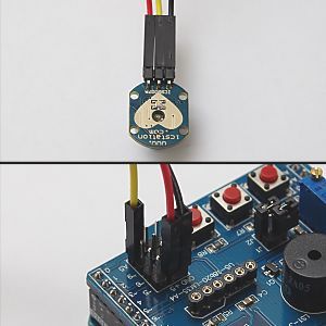
This application requires a heart beat sensor similar to the one shown in the image below, which uses light from an LED to detect pulses in a finger or ear lobe. When normalized, the sensor outputs an analogue signal of 2.5 volts, which rises and drops every time the blood flow changes due to a heart beat. The application works by counting every time the signal rises above 3 volts, then drops below 2.5 volts, and measures time between pulses to calculate the beats per minute. The beeper is sounded every time a heart beat is detected. The sensor output will need to be connected to Arduino pin A5 exposed on the multi-function shield.
WARNING: This application is not intended for medical purposes.
After powering on the Arduino, gently but firmly place the index finger on the sensor and wait for the display to start blinking. This indicates the sensor has normalized, after which the shield display will show the beats per minute, and the beeper will sound. If the display remains at 0 and doesn’t blink after several seconds, remove the finger, wait for a while and try again. Ensure the finger is placed with consistent pressure.
Possible modification for this application is to have an LED light synchronised with each heart beat.
#include <MultiFuncShield.h>
// Heart Monitor
void initializeSensorReading();
int data[4];
byte dataIdx=0;

byte pulseDetected = false;
int lastPulseTime = -1;

void setup() {
  // put your setup code here, to run once:

  MFS.initialize();
  initializeSensorReading();
  //Serial.begin(9600);
}

void loop()
{
  if (MFS.getTimer() == 0)
  {
    MFS.setTimer(10000);    // reset millisecond countdown timer.
    if (lastPulseTime != -1)
    {
      lastPulseTime = 10000 + lastPulseTime;
    }
  }

  int sensorValue = analogRead(A5);    // read the sensor.

  if (sensorValue < 20 || sensorValue > 970)
  {
    // Sensor hasn't normalized, check how long for in milliseconds.
    if (lastPulseTime != -1 && lastPulseTime - MFS.getTimer() > 700)
    {
      initializeSensorReading();
    }
  }
  else if (sensorValue > (3 * 1024) / 5)  // value is rising, so must be start of a pulse.
  {
    if (!pulseDetected)
    {
      pulseDetected = true;

      if (lastPulseTime == -1)
      {
        lastPulseTime = MFS.getTimer();
      }
      else
      {
        int pulsePeriod = lastPulseTime - MFS.getTimer();  // calculate time between pulses in millseconds.
        lastPulseTime = MFS.getTimer();

        int bpm = 60000 / pulsePeriod;    // calculate beats per minute.

        if (bpm < 45 || bpm > 230)   // bpm is outside acceptible range, so clear the data buffer.
        {
          initializeSensorReading();
        }
        else
        {
          // bpm is within range, but still need to calculate average.

          data[dataIdx++] = bpm;

          if (dataIdx >= 4)
          {
            dataIdx = 0;
          }

          if (data[0] && data[1] && data[2] && data[3])  // check if data buffer is full before calculating avg bpm.
          {
            int avgBpm = (data[0] + data[1] + data[2] + data[3]) / 4;

            MFS.blinkDisplay(DIGIT_ALL, OFF);
            MFS.write(avgBpm);
            MFS.beep();
          }
          else
          {
            // buffer not full, so blink the display.
            MFS.blinkDisplay(DIGIT_ALL, ON);
          }
        }
      }
    }
  }
  else if (sensorValue < (1024 / 2))  // value is falling, so must be end of pulse.
  {
    pulseDetected = false;
  }

  //Serial.println(sensorValue);
  //delay(10);
}

// Initialize the read buffer and display.
void initializeSensorReading()
{
  lastPulseTime = 0;

  dataIdx = 0;
  for (int i=0; i<4; i++)
  {
    data[i] = 0;
  }

  MFS.write(0);
  MFS.blinkDisplay(DIGIT_ALL, OFF);
}
Surface Incline Level Indicator
The surface level indicator application uses the MPU6050 motion sensor to determine the angle of inclination of a flat surface. You will need to download the full source code before uploading to the Arduino. Because the application uses software I2C, when using R3 boards Uno and Leonardo, use pin 5 for SCL and 6 for SDA. For Mega2560, use pin 5 for SCL and pin A5 for SDA.
After powering on the Arduino, place the motion sensor on a surface that is as level as possible, then press and hold button 1 on the multi-function shield. LED 1 blinks while the sensor is calibrated. Thereafter, by placing the motion sensor on inclined surfaces the shield will display the angle of inclination.
Presently the incline is displayed only for a single axis, but the application could modified to the show the incline for an additional axis.
#include <Wire.h>
#include <MultiFuncShield.h>

#include "I2C.h"
#include "MPU6050.h"

void calibrate();

MPU6050 MPU;

const float radToDeg = 180.0 / 3.1415926535897932384626433832795;
int xOffset=0, yOffset=0;
float zScaleOffset = 1; // multiply Z axis with this value to get as close to 1g as possible.

void setup() {
  // put your setup code here, to run once:

  // Use hardware I2C
  Wire.begin();
  I2C1.initialize(&Wire);
  MPU.initialize(&I2C1, MPU_DEFAULT_ADDRESS, ACCEL_FS_2, GYRO_FS_250, DLPF_BW_5);
#endif

  MFS.initialize();
}

void loop() {
  // put your main code here, to run repeatedly:

  byte btn = MFS.getButton();

  if (btn == BUTTON_1_LONG_PRESSED)
  {
    calibrate();
  }

  MPU.getAccelRaw();

  MPU.accel_X_Raw -= xOffset;
  MPU.accel_Y_Raw -= yOffset;

  float angle;

  if (MPU.accel_Z_Raw == 0)
  {
    angle = 90;
  }
  else
  {
    angle = atan((float)MPU.accel_Y_Raw / (MPU.accel_Z_Raw * zScaleOffset)) * radToDeg;  // calculate for y axis
    //angle = atan((float)MPU.accel_X_Raw / (MPU.accel_Z_Raw * zScaleOffset)) * radToDeg;    // calculate for X axis
  }
  MFS.write(angle, 1);
  delay(200);
}

void calibrate()
{
  MFS.write("    ");
  MFS.writeLeds(LED_1, ON);
  MFS.blinkLeds(LED_1, ON);

  // discard first few sensor readings.
  for (int i=0; i<10; i++)
  {
    MPU.getAccelRaw();
    delay(10);
  }

  int xValues[5], yValues[5], zValues[5];

  for (int i=0; i<5; i++)
  {
    MPU.getAccelRaw();
    xValues[i] = MPU.accel_X_Raw;
    yValues[i] = MPU.accel_Y_Raw;
    zValues[i] = MPU.accel_Z_Raw;
    delay(300);
  }
  xOffset = MedianOf5(xValues[0], xValues[1], xValues[2], xValues[3], xValues[4]);
  yOffset = MedianOf5(yValues[0], yValues[1], yValues[2], yValues[3], yValues[4]);

  zScaleOffset = (float)MPU.accelScaleValue / MedianOf5(zValues[0], zValues[1], zValues[2], zValues[3], zValues[4]);

  MFS.blinkLeds(LED_1, OFF);

  // clear the input button buffer by reading it and discarding value.
  for (int i=0; i<10; i++)
  {
    MFS.getButton();
  }
}
Arduino Sonar Ranger
The Arduino sonar ranger application uses the HC SR04 sonar module to measure distance between the module and a solid object up to 5 meters away. This application works in a way similar to the obstacle sensor of some vehicles that assist the driver in parking manoeuvres. As an obstacle nears the sonar module, the beeper is sounded at shorter and shorter intervals. The shield’s button 1 is used for engaging or disengaging the sonar module.
The trigger and echo pins of the sonar module are connected to Arduino pins 5 and 6 respectively, which are exposed on the multi-function shield. After powering on the Arduino, place a solid object at different distances away from the sonar module.
#include <MultiFuncShield.h>
// Sonar Ranger
const int TrigPin = 5;
const int EchoPin = 6;

enum sonarModeValues
{
  MODE_SONAR_OFF,
  MODE_SONAR_ON
};

byte sonarMode = MODE_SONAR_OFF;

void setup()
{
  //Serial.begin(9600);
  pinMode(TrigPin, OUTPUT);
  pinMode(EchoPin, INPUT);

  MFS.initialize();
  MFS.write("off");
}

void loop()
{
  byte btn = MFS.getButton();

  switch (sonarMode)
  {
    case MODE_SONAR_OFF:
        if (btn == BUTTON_1_PRESSED)
        {
          sonarMode = MODE_SONAR_ON;
          MFS.beep(5, 95, 1,0,0);
          MFS.write("on");
        }
        break;

    case MODE_SONAR_ON:
        if (btn == BUTTON_1_PRESSED)
        {
          sonarMode = MODE_SONAR_OFF;
          MFS.beep(0);
          MFS.write("off");
          MFS.blinkDisplay(DIGIT_ALL, OFF);
          MFS.initSonar();
        }
        else
        {
          int distance = MFS.getSonarDataCm(TrigPin, EchoPin);

          if (distance != 0 && distance < 2000)
          {
            int offPeriod = distance - 6;

            if (offPeriod < 0)
            {
              offPeriod = 0;
            }

            MFS.write(distance);
            MFS.setBeepOffPeriod(offPeriod);

            MFS.blinkDisplay(DIGIT_ALL, distance < 11);
          }
          delay(100);
        }
        break;
  }
}
Arduino Speedometer
The Arduino speedometer application calculates the speed of a wheel (in kilometres/hour) by using a magnet and a reed switch, which is connected to Arduino pin 5. It should also be possible to fabricate your own wheel encoder using a line or mark sensor.
After powering on the Arduino, press and hold button 1 of the multi-function shield until the display blinks, then use buttons 2 and 3 to set the wheel diameter in centimetres. Press button 1 again when finished. Turn the wheel to see the speed indicated on the shield display.
A possible enhancement for this application is to keep a record of trip distance in kilometres.
#include <MultiFuncShield.h>
// Speedometer
enum SpeedoModeValues
{
  SETUP_WHEEL,
  CALCULATE_SPEED
};

byte speedoMode = CALCULATE_SPEED;
byte wheelDiameterCm = 60;
unsigned int wheelCirmcumferenceCm = (wheelDiameterCm * 314) / 100;

float SpeedKmh (unsigned int wheelCircumferenceCm, unsigned int periodMs);


void setup() {
  // put your setup code here, to run once:

  pinMode(5, INPUT_PULLUP);

  MFS.initialize();

  MFS.initPulseInCounter(
      5,                 // use digital pin 5 for pulse input.
      2000,              // the number of milliseconds to wait for a pulse, before resetting pulse in period to 0.
      LOW                // trigger pulse on LOW input.
  );
}

void loop() {
  // put your main code here, to run repeatedly:

  byte btn = MFS.getButton();

  switch (speedoMode)
  {
    case SETUP_WHEEL:
        if (btn == BUTTON_1_PRESSED)
        {
          speedoMode = CALCULATE_SPEED;
          MFS.blinkDisplay(DIGIT_ALL, OFF);
          wheelCirmcumferenceCm = (wheelDiameterCm * 314) / 100;
        }
        else if (btn == BUTTON_2_PRESSED || btn == BUTTON_2_LONG_PRESSED)
        {
          wheelDiameterCm--;

          if (wheelDiameterCm < 30)           {             wheelDiameterCm = 30;           }           MFS.write(wheelDiameterCm);         }         else if (btn == BUTTON_3_PRESSED || btn == BUTTON_3_LONG_PRESSED)         {           wheelDiameterCm++;                      if (wheelDiameterCm > 100)
          {
            wheelDiameterCm = 100;
          }
          MFS.write(wheelDiameterCm);
        }
        break;

    case CALCULATE_SPEED:
        if (btn == BUTTON_1_LONG_PRESSED)
        {
          speedoMode = SETUP_WHEEL;
          MFS.write(wheelDiameterCm);
          MFS.blinkDisplay(DIGIT_ALL, ON);
        }
        else
        {
          unsigned int pulsePeriodMs = MFS.getPulseInPeriod();

          if (pulsePeriodMs == 0)
          {
            MFS.write(0.0, 1);
          }
          else
          {
            MFS.write(SpeedKmh(wheelCirmcumferenceCm, pulsePeriodMs), 1);
          }
        }
        break;
  }
  delay(100);
}

float SpeedKmh (unsigned int wheelCircumferenceCm, unsigned int periodMs)
{
  return (float)(wheelCircumferenceCm * 36) / periodMs;
}
All the code samples and applications have been tested and work. If you experience any difficulties, please post a comment, and we’ll get back to you as soon as we can.
Thank you Kashif.
Straight forward and clean videos and codes.
Please work on more examples that explore the Bluetooth and voice recognition modules if you have not done so….
Thanks again!
Hi, I’m still beginners to programming with Arduino, I tested the sketch on the countdown timer and I questions:
1 – you can flash the “.” between the minutes and seconds?
2 – you can bring up the word “0:00” when the set and making sure that when the tens of minutes and seconds in the count ends, the display appears in place “0”, for example 59 seconds so visaulizzati “0:59” or 1 minute and 9 seconds show “01/09”
3 – last question, you can get a list of commands in this shield with its syntax?
Thank you in advance.
Thank you for this series on the multi functional shield. You have created some best sketches for this shield I can find anywhere. Thanks again for your great work and I wish you all the best.
Thank you guys. There a few other sketches in the pipeline, for this and other shields, although the supporting content (video and text) takes a long time to put together. I hope to publish these soon.
Just a BIG thank you!
Excellent piece of work, and all worked like a charme!
Bo
Hello and thank you for your work.
I try for over 3 hours at sonarRanger that under a certain distance in addition all the LEDs flash. Can you help me here? Thank you in advance.
Thank you Kashif, very good job, please could you tell me how to put the count down every second until I finish the time on the counter? A beep bep every second.
Hello thanks for the program and I put the buzzer to work, I have a problem, I want to add a relay for when I finish the count back jump and I activate a siren but no, it activates no pin … what is the problem? Thank you
Arduino: 1.8.1 (Windows 10), Плата:”Arduino/Genuino Uno”
C:\Users\User\AppData\Local\Temp\arduino_modified_sketch_556892\sketch_mar05a.ino:1:22: fatal error: TimerOne.h: No such file or directory
#include
^
compilation terminated.
exit status 1
pleas help me
why that problem?
many thanks
Hi. Please ensure you have downloaded and correctly installed the necessary libraries from this link:
https://www.cohesivecomputing.co.uk/hackatronics/arduino-multi-function-shield/
I hope that helps.
Hi
Perfect for my sons project using a coutdown timer – thanks!
But i too would like to add a decimal point between the minutes and seconds – could you advise please.
I was thinking either something to simply write the dot permanently or else to do some maths and make the minutes seconds as 100 times smaller to get the decimal point?
Any ideas please?
Thanks again
Mark
Hi Mark. In my response to Claudio here, there is an example of using decimal point for separation of minutes and seconds using a new function displayCountdown(). Hope that helps.
Very good video series, I just got one of these shields, the one with all the words misspelled, (perhaps I should go to China and hire out as a proofreader for electronic devices!) these are all great, however I, like, I am sure, many of your viewers live in a metric deprived nation called the United States of America, so all the centimeters and meters and such have very little meaning to us over on this side of the pound. I have, in the past added conversions to many of the posted sketches but it would be great if say a second version could be posted for folks such as we who would not know a mm from a cm or a degree C from a degree K.
Hi Jerry
Thanks for the feedback. Here in the UK there are still people who remain more comfortable with inches, feet and yards etc 🙂 I’m guessing you’re referring to the sonar range finder and speedometer. I’ll see if I can put some conversion code on the web pages for the imperial units. I hope that will help.
Kashif
Please work on more examples that explore the Bluetooth and voice recognition modules
thank you so much for all !
Please comment and help,
Arduino:1.6.13 (Windows 7), Kart:”Arduino/Genuino Uno”
C:\Users\KürÅŸad\AppData\Local\Temp\Rar$DIa0.264\_24_hr_Alarm_Clock\_24_hr_Alarm_Clock.ino: In function ‘void setup()’:
_24_hr_Alarm_Clock:45: error: ‘clockISR’ was not declared in this scope
C:\Users\KürÅŸad\AppData\Local\Temp\Rar$DIa0.264\_24_hr_Alarm_Clock\_24_hr_Alarm_Clock.ino: In function ‘void loop()’:
_24_hr_Alarm_Clock:62: error: ‘displayTime’ was not declared in this scope
“MultiFuncShield.h” için birden fazla library bulundu
Kullanılıyor: C:\Users\Kürşad\Documents\Arduino\libraries\MultiFuncShield-Library
Kullanılmıyor: C:\Program Files (x86)\Arduino\libraries\MultiFuncShield-Library
“TimerOne.h” için birden fazla library bulundu
Kullanılıyor: C:\Users\Kürşad\Documents\Arduino\libraries\TimerOne-master
Kullanılmıyor: C:\Users\Kürşad\Documents\Arduino\libraries\TimerOne-v9
Kullanılmıyor: C:\Users\Kürşad\Documents\Arduino\libraries\TimerOne-v8
Kullanılmıyor: C:\Users\Kürşad\Documents\Arduino\libraries\TimerOne-v7
Kullanılmıyor: C:\Users\Kürşad\Documents\Arduino\libraries\TimerOne-v2
Kullanılmıyor: C:\Users\Kürşad\Documents\Arduino\libraries\TimerOne-v1
Kullanılmıyor: C:\Users\Kürşad\Documents\Arduino\libraries\TimerOne-r11
exit status 1
‘clockISR’ was not declared in this scope
This report would have more information with
“Show verbose output during compilation”
option enabled in File -> Preferences.
please could I have the schematic drawing by email
Thanks
jimmy meade tonabrucky rahoon galway city ireland
Hi Jimmy, the link to the schematic is here: https://files.cohesivecomputing.co.uk/Multifunction-Shield.pdf
I don’t understand the usage of “delay(100)” in line 98 of the countdown sketch. Why do you include the TimerOne library and then use this stupid delay function?
Hi Fred, it’s possible that line is just vestigial code.
Hi, works really well. Thank. Two questions: why i hear a beep noise from the buzzer continually? 2-Is it possible to duplicate the display to be shown in another room with a 4 digits 7 segments module (4 wires: vcc gnd dio clk) ? Thanks!
Hi. It seems there are shields with buzzers that are different to the one I have on my shield, and as such the code in the library is not suitable for it. Unfortunately, I don’t have access to this type of buzzer at the moment.
You would need the same bit shifting circuit to duplicate the display with just 4 wires.
How does one combine some of the above examples into one, multi-tasking function?
E.G. having a 24 hr clock, plus having a countdown-timer (with the press of a button),
or alternating the 4-digit, 7-segment display between a Temperature display (with LM35 sensor) and the 24hr Real Time Clock for example?
Jeff – As of 1/25/2020 this does NOT work. But added the following fixes
1. #include // Added in #include area
Inside void setup();
2. Timer1.initialize(); // added by Jeff ?? To Fix code
3. MFS.initialize(); should be MFS.initialize(&imer1);
Nice program. All is good.
My comment applies to he first program above, the timer countdown. I should have noted that.
Hello Jeff, the most recent versions of the library (v 1.3) and source code no longer use Timer1. It’s possible you still have the older version.
Hi to all,
I modified the 24h alarm clock’s displayTime function to insert a dot “.” betwen hours and minutes.
Here my source:
void displayTime (byte hours, byte minutes)
{
char time[6];
char trime[6];
sprintf(trime, “%4d”, (hours * 100) + minutes);
time[0]=trime[0];
time[1]=trime[1];
time[2]=((char)46);
time[3]=trime[2];
time[4]=trime[3];
MFS.write(time,2);
}
Thank you Davide for this modify.
Can you show me how can I set 3 (or more) alarms in a day? And how can I set the alarm to be silence after 30 seconds?
Can you show me how can I set 3 (or more) alarms in a day? And how can I set the alarm to be silence after 30 seconds?
Hi Hashib , Hope you are doing well . I need your support . all examples works fine but i dont know why segment B on display remains on almost always . Thank you
Hi Sergio, it’s possible the USB connector is making contact with the segment pins. If so, try using insulation tape.
OMG! I spent hours trying to figure this out. Put electric tape and..voila! Thanks. BTW, Claude’s solution was to make the digit blink for 5 and 6 so they can be differntiated from 9 and 8. Pretty clever…
how i can use the 24 hour alarm clock code with ds1302 rtc module
In the count down timer
Replacing all lines with “ MFS.Write(minutes*100+seconds); “
With these two line puts a decimal place between minutes and seconds
float time=(minutes*100+seconds);
MFS.Write (time/100, 2);